
Angular contact ball bearings – applications, design and selection Angular contact ball bearings are used where a shaft carries radial and axial loads simultaneously a...
Angular contact ball bearings – applications, design and selection
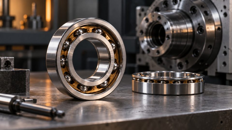
Angular contact ball bearings are used where a shaft carries radial and axial loads simultaneously and the arrangement must retain high stiffness, guidance accuracy and high-speed capability. Compared with deep groove ball bearings, they have asymmetrical raceways. The line joining the ball's contact points with the raceways is inclined relative to the radial plane, forming a contact angle. This enables the bearing to carry combined loads effectively.
This design nevertheless requires deliberate mounting. A single-row angular contact bearing mainly carries axial force in one direction, while radial load creates an additional axial component. These bearings therefore often operate in pairs or sets. Arrangement life depends on dimensions, contact angle, pair configuration, clearance or preload, accuracy class, fit, lubrication and load direction.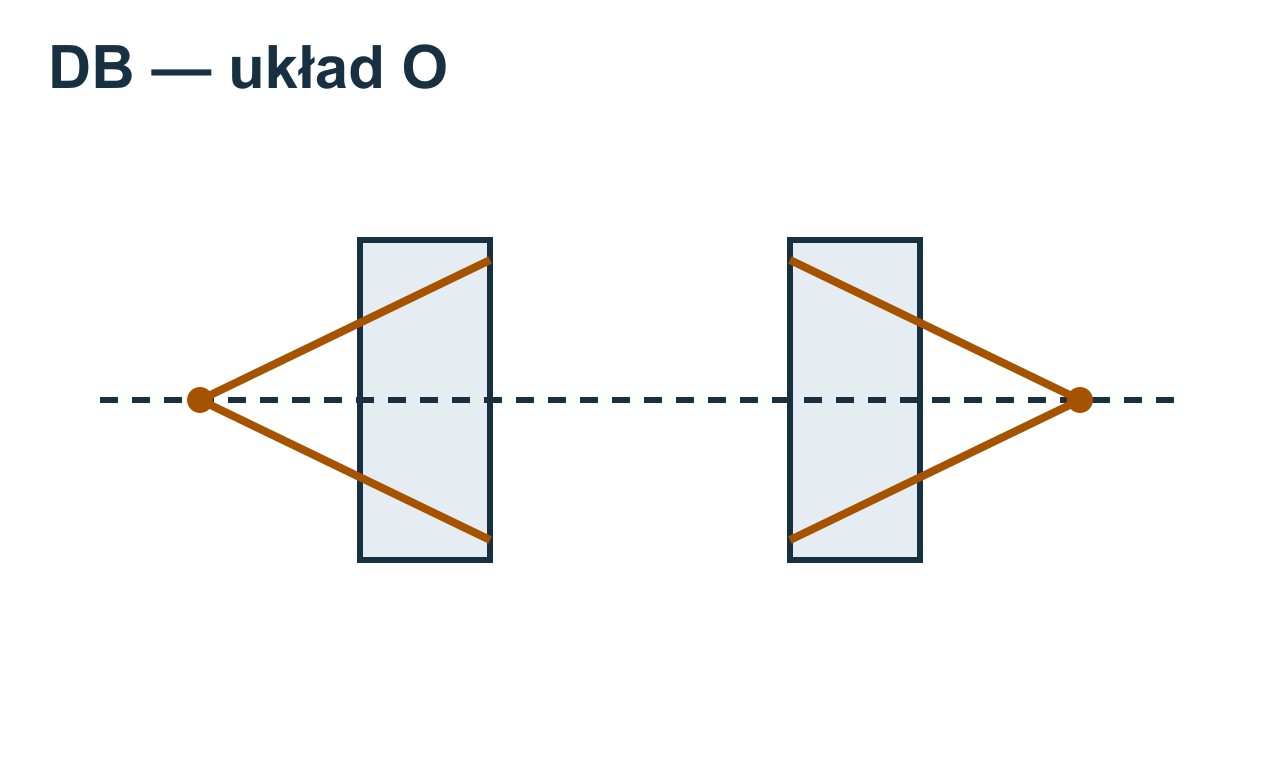 The force action lines diverge towards the outside of the pair (O arrangement). This simplification does not specify the contact angle or preload setting.
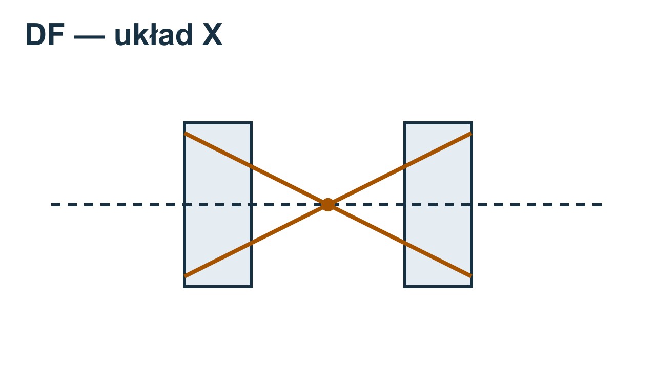 The force action lines converge between the bearings (X arrangement). This simplification does not specify the contact angle or preload setting.
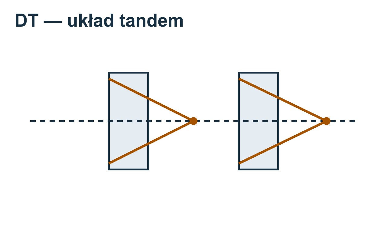 The bearings face the same direction. A tandem pair carries axial load in one direction. This simplification does not specify the contact angle or preload setting.
How does an angular contact ball bearing work?
In a deep groove ball bearing, raceway geometry is approximately symmetrical. In an angular contact bearing, the raceway shoulders have different heights, so the load passes through the rolling elements at a defined angle. The greater the contact angle, the greater the ability to carry axial forces relative to radial forces. A smaller angle generally favours higher rotational speeds.
Typical angles found in industrial and precision bearings include 15°, 25°, 30° and 40°, but letter designations differ between manufacturers. Do not assume that the same suffix always means the same angle. When changing brands, check the designation table, internal geometry and whether the bearings can be paired.
A single-row angular contact bearing can carry axial load in the direction in which the action lines are supported by the higher raceway shoulders. If axial forces occur in both directions, two opposing bearings or a double-row bearing are usually used. Correct orientation is essential for proper operation. Reversing one component may deprive the arrangement of the required axial load rating.
Main types of angular contact bearings
Type Loads carried Typical application Key consideration |
Type Loads carried Typical application Key consideration |
Type Loads carried Typical application Key consideration |
Type Loads carried Typical application Key consideration |
Type Loads carried Typical application Key consideration |
A double-row bearing is compact and easy to mount, but a pair of single-row bearings gives more freedom in selecting spacing, angle, load rating and preload. Precision applications should not use a pair made from two arbitrary bearings. Matched bearings are manufactured and marked so that clamping the rings produces the intended axial clearance or preload.
DB, DF and DT arrangements – how do they differ?
O arrangement, or back-to-back – DB
In a DB arrangement, the action lines diverge outwards, forming a shape resembling the letter O. The pair carries radial loads and axial loads in both directions. The large spacing between effective pressure centres provides high moment stiffness, so the O arrangement is often used in spindles, hubs, pumps and assemblies subject to tilting moments.
The DB arrangement tolerates misalignment and shaft deflection less well than DF. If the seats are not aligned or the shaft deflects excessively, pressure can concentrate at raceway edges. Housing manufacturing accuracy is therefore part of the selection process, not merely a mounting matter.
X arrangement, or face-to-face – DF
In a DF arrangement, the action lines converge towards the centre and resemble the letter X. The bearings also carry axial forces in both directions, but the effective spacing between pressure centres is smaller. Moment stiffness is lower than in an O arrangement, while the configuration may better tolerate slight misalignment caused by shaft deflection.
Tandem arrangement – DT
In a DT arrangement, the action lines are parallel. Two bearings jointly carry a greater axial load, but only in one direction. If axial force can reverse, the tandem set requires an additional bearing or a second set facing the opposite direction. The load is not always shared exactly equally. Manufacturing deviations, housing stiffness and the way the set is preloaded all have an effect.
Configuration Axial force Moment stiffness Misalignment tolerance Main application |
Configuration Axial force Moment stiffness Misalignment tolerance Main application |
Configuration Axial force Moment stiffness Misalignment tolerance Main application |
Where are angular contact ball bearings used?
Machine tool spindles and motor spindles
Spindles demand rotational accuracy, stiffness, low runout and high-speed capability. Pairs or sets of precision angular contact bearings are used, often with a small contact angle and controlled preload. Greater preload improves stiffness but increases friction and temperature. Selection requires a balance between machining quality, speed and grease life.
Pumps and compressors
Pump and compressor rotors generate radial and axial loads dependent on pressure, flow direction and operating point. Angular contact bearings stabilise shaft position and carry axial force. In screw, centrifugal and scroll compressors, high speed, temperature and control of rotor axial movement are important. Configuration and contact angle must suit the actual force direction.
Gearboxes and geared motors
Helical, bevel and worm gears generate axial components. Angular contact ball bearings can guide a shaft at moderate loads and high speeds, especially where low resistance to motion matters. Tapered or spherical roller bearings may be more suitable for very heavy or impact loads. The decision should be based on calculated life and stiffness.
Ball screws and linear drives
Ball screw supports must limit axial movement because any clearance translates into positioning error. Matched pairs of preloaded angular contact bearings are used, sometimes in double or multi-row arrangements. Correct abutment surfaces, controlled nut clamping and the specified bearing orientation are essential.
Motors, fans and blowers
Double-row angular contact bearings or suitable pairs can operate in compact drive systems where axial force occurs alongside radial load. Before use, compare permissible speed, heat generation and noise requirements with the parameters of a deep groove ball bearing.
Robotics and rotary tables
Mechanisms requiring accurate positioning use angular contact bearings, multi-row assemblies or four-point contact bearings. They offer a combination of axial load rating, stiffness and compact installation. Selection depends on tilting moment, motion cycle, accelerations and required accuracy.
How to select an angular contact bearing step by step
- Determine load magnitudes and directions. Record radial, axial and moment loads and their variation. Check whether axial force acts continuously in one direction or reverses.
- Establish speed and duty cycle. Maximum speed is only part of the picture. Operating time, startup frequency, acceleration and temperature under steady conditions also matter.
- Select the design type. Decide whether a single-row bearing with opposing support, a double-row bearing, a universally matchable pair, a tandem set or a precision solution is required.
- Select the contact angle. A greater angle increases axial force capacity, while a smaller angle generally favours high speed. Always compare catalogue data for the specific series.
- Select the pair configuration. DB provides high moment stiffness, DF better tolerates slight misalignment, and DT increases axial load rating in one direction.
- Specify clearance or preload. Preload improves stiffness and accuracy but increases friction and temperature. Do not choose a heavier preload just in case.
- Check fits and surface tolerances. An interference fit changes operating clearance and preload. Shape errors in the journal, seat or abutment surface can cause uneven loading.
- Select accuracy class, cage and design. A spindle may require a precision class, special cage and limited runout, while a typical pump may use a standard design.
- Select lubrication and sealing. Consider speed, temperature, contamination and maintenance access. Too much grease can raise temperature just as effectively as too little.
- Verify the life and temperature of the entire bearing arrangement. Calculations should account for load distribution within the pair, induced forces, preload, shaft and housing stiffness, and thermal conditions.
Preload – when does it help and when does it harm?
Preload is a controlled internal load in the absence of external load. It eliminates clearance, increases stiffness and improves guidance accuracy. It can also limit ball sliding under certain conditions. It is therefore common in machine tools, ball screw supports and precision drives.
These benefits have a cost: greater preload increases frictional torque, heat generation and sensitivity to mounting errors. An interference fit, shaft thermal expansion, temperature differences between rings and nut tightening can increase operating preload further. In extreme cases, the arrangement overheats despite correct lubrication.
The safest approach is to use factory-matched pairs of the specified preload class and mount them according to their markings. Grinding spacer rings or selecting clamping force without manufacturer data requires experience and measurement control. In a production machine, retain the original set designation, not merely the diameter and series.
Mounting and operation – practical guidance
- Before mounting, check arrows, lines and markings on the rings. They indicate orientation and how the bearings should be assembled.
- Do not separate a factory-matched pair or mix its components with other bearings.
- Transmit mounting force only through the ring being installed with interference. Do not transmit blows through balls and raceways.
- Check abutment-surface squareness and journal and seat runout. Angular contact bearings are sensitive to deviations.
- Tighten nuts according to procedure. Excessive clamping may unintentionally increase preload.
- Use clean tools and a clean mounting workstation. Small contaminants cause local pressure and noise.
- Select the correct grease quantity. In high-speed arrangements, overfilling the free space causes intensive grease churning and a temperature rise.
- After startup, monitor temperature, vibration, noise and power consumption. Assess stabilisation over time, rather than only a few minutes after starting.
Common errors when selecting angular contact bearings
- Treating a single-row bearing as bidirectional. A single bearing usually does not secure the shaft against axial force in the opposite direction.
- Reversing a bearing in a pair. Incorrect orientation changes the DB, DF or DT arrangement and can deprive the assembly of the expected load rating.
- Pairing arbitrary bearings. Two bearings of the same dimensions do not necessarily form a correctly matched pair.
- Selecting by basic designation alone. Contact angle, universal design, preload, accuracy class, cage and sealing also matter.
- Excessive preload. It may improve stiffness when cold but cause excessive friction and reduced life after warming up.
- Overlooking induced axial force. Radial load in an angular contact bearing generates an axial component that another element in the arrangement must balance.
- Inaccurate housing. A precision-class bearing cannot correct alignment and squareness errors.
- Incorrect lubrication. Both too little and too much lubricant can increase temperature and damage raceways.
FAQ – angular contact ball bearings
How does an angular contact bearing differ from a deep groove ball bearing?
It has asymmetrical raceways and a defined contact angle, enabling it to carry combined radial and axial loads more effectively. A single-row design usually carries axial force mainly in one direction.
Can a single angular contact bearing carry axial force in both directions?
A standard single-row angular contact bearing is mainly intended for one direction. Bidirectional forces require an opposing pair, a double-row bearing or a suitable four-point contact design.
Which is stiffer: a DB or DF arrangement?
The DB, or O, arrangement has greater effective spacing between pressure centres and usually higher moment stiffness. The DF arrangement has a smaller spacing but may better tolerate slight deviations caused by shaft deflection.
What does a greater contact angle provide?
It increases axial load capacity but may restrict limiting speed compared with a smaller-angle design. Selection must account for the ratio of axial to radial force and speed.
Can any two bearings be assembled into a pair?
In less demanding applications, a design sometimes allows individual clearance adjustment, but two bearings must not automatically be treated as a precision pair. Controlled clearance or preload requires matched or universal bearings in accordance with the manufacturer's catalogue.
Do angular contact bearings require preload?
Not always. Preload is used where high stiffness, accuracy and reduced clearance are required. Other arrangements may require a defined axial clearance. The value follows from the design and thermal conditions.
How can the mounting direction be identified?
Use ring markings and manufacturer instructions. The geometry of the higher raceway shoulders and lines or arrows on the sides indicate orientation. Appearance alone is not always sufficient for universal sets.
Why does a new angular contact bearing heat up after mounting?
Possible causes include excessive preload, an excessively tight fit, too much grease, misalignment, incorrect pair orientation or excessive speed. Assess temperature together with vibration, torque and lubrication conditions.
Need help selecting an angular contact bearing?
Prepare the full designation of the existing bearing, dimensions, axial force direction, speed, temperature and machine description. This makes it easier to verify the series, contact angle, configuration and preload. Explore the available angular contact ball bearings in the NERON shop or contact the sales department if you need help identifying a replacement.
Summary
Angular contact ball bearings are a good choice for arrangements under radial and axial loads, particularly where speed, stiffness and accurate shaft positioning matter. Their capabilities nevertheless depend on correct orientation. The DB arrangement provides high moment stiffness, DF better accommodates slight deviations, and DT increases axial load rating in one direction.
Before purchase, check dimensions, contact angle, single or matched design, force directions, clearance or preload, accuracy class and lubrication conditions. Retaining the original set's full designation is safest when machine conditions have not changed. New or modified designs should involve calculations for the entire bearing arrangement and temperature verification after startup.
Related categories
- Angular contact ball bearings
- Ball bearings
- Tapered roller bearings
- Cylindrical roller bearings
- All bearings
Related articles
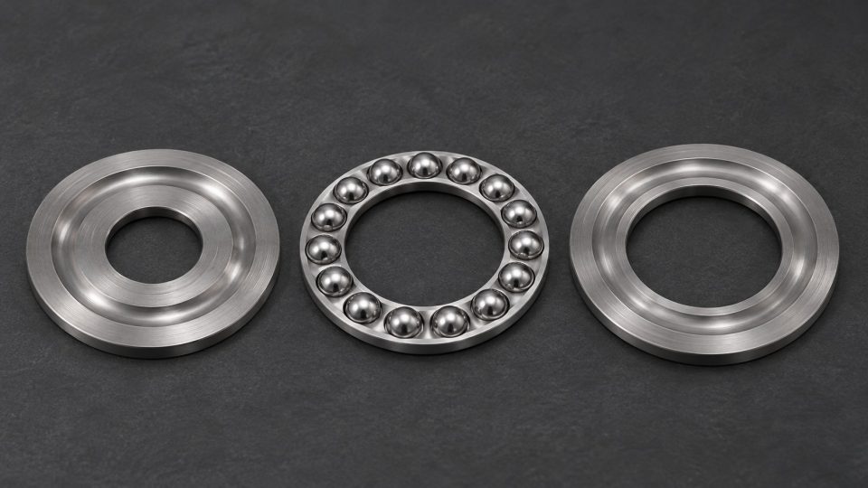
Łożysko oporowe 51105 czy 51205? Co zmierzyć przed wymianą
Okładka pokazuje rozłożone części poglądowo. Wymiary odczytaj z karty danego wykonania. Łożysko 51105 ma wymiary 25 × 42 × 11 mm, a 51205 ma 25 × 47 × 15 mm. Oba mają ...
Read article · 3 min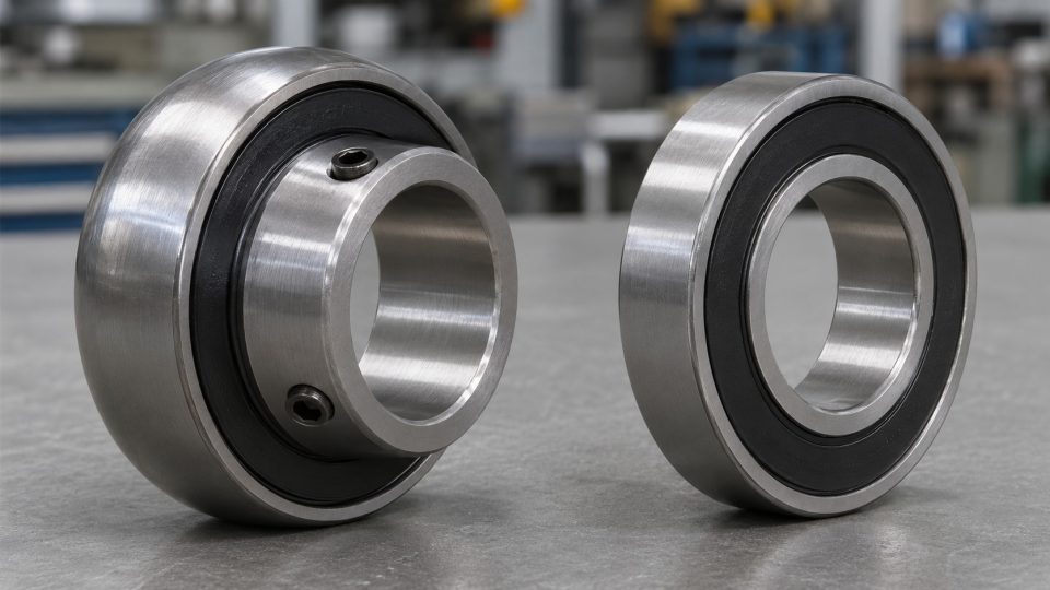
UC205 a 6205 — dlaczego wymiary 25 i 52 mm nie wystarczą?
UC205 i 6205 nie są bezpośrednimi zamiennikami tylko dlatego, że mają otwór 25 mm i średnicę zewnętrzną 52 mm. Przy zakupie sprawdź również kształt powierzchni zewnętr...
Read article · 3 min
causes of premature bearing wear
Causes of premature bearing wear – mounting errors, lubrication and contamination The most common causes of premature bearing wear are inadequate lubrication, lubrican...
Read article · 12 min