
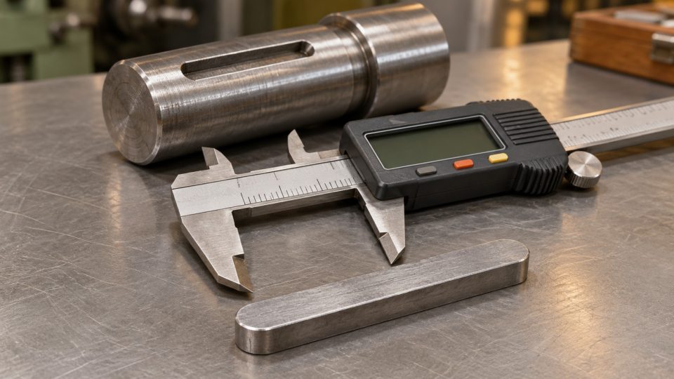
A DIN 6885 parallel key is selected to suit the shaft and hub keyways, not solely the shaft diameter. Before purchasing, establish the width b, height h, length l, end...
A DIN 6885 parallel key is selected to suit the shaft and hub keyways, not solely the shaft diameter. Before purchasing, establish the width b, height h, length l, end shape and drawing requirements. The designation 10 × 8 × 100 mm describes three different dimensions. It does not confirm that the part fits every shaft with a 10 mm wide keyway.
The following procedure helps identify the part and prepare a replacement order. It does not replace calculating the joint for the transmitted torque or assessing a worn shaft and hub.
What do b, h and l mean in a key designation?
Check the drawing in the key's catalogue data sheet, as the trade name may use the abbreviated term “wedge”. For the parallel key shown, the three dimensions are read as follows.
- b — width the dimension between the two long side faces, across the key.
- h — height the thickness of the component between its bottom and top faces.
- l — overall length the dimension from one end to the other, along the key. With rounded ends, it also includes the rounded portions.
Do not interchange width and height. A rectangular cross-section of 10 × 8 mm does not mean a square of 10 × 10 mm. State the end shape separately. Catalogue form A has rounded ends. The notation b × h × l alone does not convey this information.
How do you measure an old key, and what cannot be inferred from the measurement?
- Prepare the part for inspection. Clean it and inspect the sides and ends. Note dents, burrs, cracks and signs of movement. Do not remove material from the measuring surfaces to obtain the expected size.
- Measure width and height separately. Measure on flat surfaces, away from chamfers, rounded edges and visible damage. Repeat the measurement at several locations. Record differing results instead of choosing the most convenient value.
- Measure the full length and photograph the ends. Do not measure only the straight section between the curves. Include a top view and a side view with your enquiry.
- Compare the result with the assembly drawing. A worn or deformed specimen is an identification aid, not a tolerance reference. Select the instrument and measuring method to suit the required accuracy. A calliper alone does not confirm every fit.
If there is no drawing, state this in the enquiry. Do not turn a reading of “approximately 10 mm” into confirmation of the nominal width and tolerance. Repairs may also require measurements of both keyways by the person assessing the assembly.
Why is a matching cross-section insufficient?
The key, shaft keyway and hub keyway form a single joint. Manufacturers' documentation distinguishes between the width tolerances of the two keyways and the seating arrangements. Establish the required fit instead of assuming that every part with the same nominal b will fit and function correctly.
Also check the keyway depths and the key's position in cross-section. Technical data sheets distinguish DIN 6885-1 and DIN 6885-2. The difference primarily concerns the radial position of the key. Do not transfer dimensions from an arbitrary table without checking its heading and drawing. The height of the key itself is not the keyway depth.
Do not select the length solely according to the available space. The joint requirements, end geometry and assembly documentation must agree. If the keyway sides are battered, ordering a wider key does not replace diagnosis and approval of the repair.
Order example — 10 × 8 × 100 mm key
The NERON range includes a 10 × 8 × 100 DIN 6885 parallel key, 2 pieces. The data sheet states
- b = 10 mm — width
- h = 8 mm — height
- l = 100 mm — length
- uncoated steel, pack of 2 pieces.
This is an example of reading a specific data sheet. It does not confirm the steel grade, the tolerance of every surface, the end form or the load capacity in your machine. If the drawing requires a specific variant or material document, check these details before purchasing.
What should you send in a replacement enquiry?
State b × h × l, the standard and its part specified in the drawing, end form, material and required tolerances. Include photographs, shaft diameter, available keyway data and whether you are replacing an undamaged part or repairing a worn joint. Distinguish measured dimensions from those required by the documentation.
Also check how axial location is achieved in the assembly. If it involves a retaining ring, see the separate guide DIN 471 or DIN 472 — selecting a retaining ring for a shaft or bore. Selecting a key and selecting a retaining ring require different data.
The most reliable order describes the part, both keyways and the assembly requirements. The phrase “key for a shaft” or an approximate dimension of a worn specimen leaves too many unknowns.
Related articles
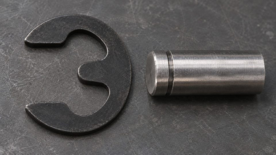
Płytka osadcza DIN 6799 — co oznacza rozmiar 8 mm?
Jeśli wymieniasz płytkę osadczą DIN 6799, sprawdź najpierw średnicę na dnie rowka. W oznaczeniu DIN 6799–8 liczba 8 odnosi się do nominalnej średnicy rowka d₂. Średnic...
Read article · 3 min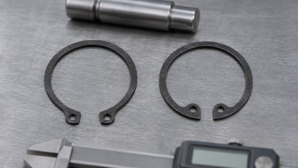
DIN 471 or DIN 472 circlip? How to select the size
DIN 471 denotes a retaining ring for a shaft, while DIN 472 denotes a ring for a bore. Before purchasing, establish the installation location, nominal shaft or bore di...
Read article · 5 min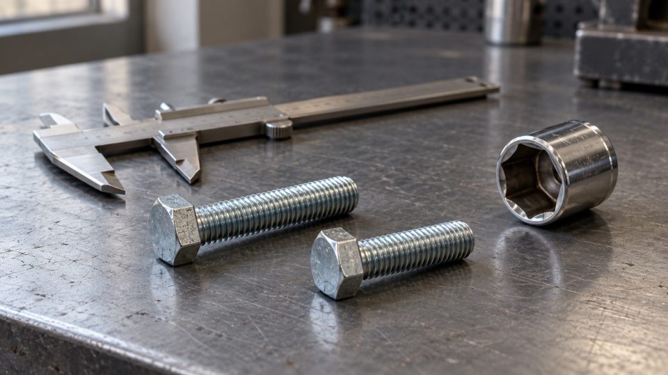
DIN 933 and ISO 4017 — which wrench and what to check before replacement?
An M10 bolt does not always require a 17 mm wrench. For DIN 933, the nominal width across flats is 17 mm, while for ISO 4017 it is 16 mm. The same thread therefore doe...
Read article · 4 min